
.jpg)
Finite Element Analysis (FEA) enables engineers to test a design virtually, before building it. NCES uses FEA consulting services to reveal weak spots early. This kind of analysis ranks among the best finite element analysis companies in India for precise, trustworthy predictions.
Choosing the right analysis type determines project success. You could run static, modal, or vibration analysis. Each serves a distinct need. Picking the wrong one wastes time and money. It may even hide design flaws until it is too late.
Static analysis checks structural response under steady loads. Modal analysis finds natural frequencies and mode shapes. And vibration analysis assesses responses under dynamic loads—harmonic, random, shock.
NCES has deep experience in 5G/Telecom, Aerospace, Semiconductor, and Medical Devices. They offer robust FEA consulting services, acting as one of Indias top finite element analysis companies. They deliver across static, modal, and vibration simulations for high‑tech sectors.
Static Analysis: The Cornerstone of Structural Design
Static analysis examines structures under steady loads. Forces do not change with time. When structures are in equilibrium, acceleration is zero. Loads are balanced by reactions. Structure is stable.
You can model point loads, distributed loads, thermal expansion, and pressure. It is versatile yet simple. Linear static assumes elastic material and small deformation. Nonlinear includes plasticity or large displacement.
Key Applications and Industry Use Cases
Static analysis is the first check in many design workflows.
• Semiconductor Industry: Parts on PCBs and heat sinks face thermal and mechanical loads. Static analysis ensures mounts do not fail.
• Medical Devices: Device enclosures must resist loads applied by users or internal components.
• Aerospace & Defense: Static simulation validates support beams, platforms, or ground frames under load.
• 5G/Telecom: Static analysis verifies telecom chassis under rack and mounting loads.
Advantages
• Fast computation
• Simpler models
• Straightforward interpretation
Limitations
• No insight into vibration or fatigue
• Cannot handle time-varying loads
• Misses dynamic effects like shock or impact
Best Practices for Static FEA
Small mistakes can mislead results.
• Proper boundary condition setup - Fix nodes or surfaces correctly. Wrong support data skews stresses.
• Material property selection - Choose correct elasticity, yield strength, thermal expansion.
• Mesh refinement strategies - Use finer mesh near stress concentrations or load points.
• Result interpretation and safety factor application - Always compare stress results to allowable limits and use conservative safety factors.
Modal Analysis: Understanding Natural Behavior
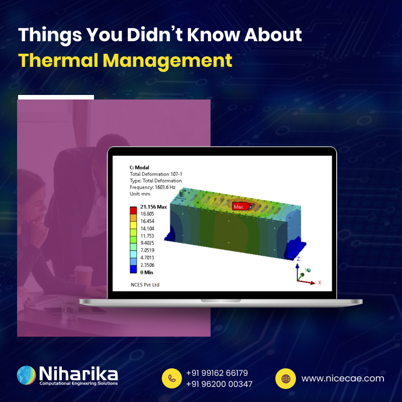
Modal analysis determines how a structure vibrates naturally. And each mode has a frequency and a shape that shows deformation pattern.
Mathematically, it solves eigenvalue equations using mass and stiffness matrices. The stiffness matrix resists deformation. Mass matrix represents inertia. It also assumes free vibration without any external forces.
Critical Applications Across Industries -
Modal analysis helps avoid resonance and vibration issues.
• Data Centers: Server racks must avoid frequencies caused by fans or equipment vibration.
• HVAC Systems: Ductwork vibration mode analysis. Resonance in large ducts under air pressure can cause fatigue or noise.
• Process Industry: Pipe system modal characteristics. Pipes full of fluid may resonate under flow-induced excitation.
• Telecom Equipment: Avoiding resonance with operational frequencies. RF equipment should not vibrate at frequencies used during operation.
Modal Analysis Output Interpretation
Interpretation is more than numbers.
• Mode shapes visualization and physical meaning - Graphical shapes show where deformation is strongest.
• Effective mass participation factors - They show how much mass participates in each mode.
• Frequency separation requirements - Modes should be well separated from operational frequency ranges.
• Modal damping considerations - Real systems have damping. That reduces amplitude near resonance.
Integration with Design Process
Early modal checks save redesign later.
• Early‑stage design optimization - You can tune stiffness or mass to shift natural frequencies early on.
• Resonance avoidance strategies - Add stiffeners or change geometry to shift modes away from critical ranges.
• Material and geometry modifications for frequency tuning - Heavier or stiffer materials alter modal behavior.
• Validation with experimental modal testing - Match FEA results to lab tests to verify accuracy.
Understand why root cause analysis is critical for preventing costly downtime.
Vibration Analysis: Dynamic Response Evaluation
It studies how structures respond under time‑varying loads — from constant pulses to random shocks.
Types of Vibration Analysis in FEA
Different methods suit different loading types.
• Harmonic Analysis: Sinusoidal loading response. A periodic force at fixed frequency, like motor vibration. Applied when the force varies in a sine wave — like rotating equipment.
• Random Vibration: Statistical approach for random loading. Used when loads vary randomly—e.g. transport, road conditions. Uses a statistical approach — ideal for seismic or road transport loads.
• Sine Sweep Analysis: Frequency‑dependent response evaluation. Frequency is swept over a range, typical in equipment testing. Tests a range of frequencies — often used in qualification testing.
• Shock Analysis: Transient dynamic response. Short, high‑intensity load—for example drops or impacts. For sudden impacts — evaluates transient responses.
Industry‑Specific Vibration Challenges
Each industry has its own vibration norms.
• Semiconductor: Transportation and operational vibration effects. Sharp shocks or random vibrations can damage ICs or packaging.
• Medical Devices: Compliance with medical equipment standards. Devices must meet vibration limits during shipping and operation.
• Defense: MIL‑STD vibration requirements. Defense equipment follows strict standards under shock, sine sweep, random vibration.
• 5G Equipment: ETSI EN 300 019‑2‑2 standard compliance. Telecom hardware must survive standard vibration tests.
Advanced Vibration Analysis Techniques
• Response spectrum analysis for seismic applications - Useful if base excitation comes from earthquakes.
• Power spectral density (PSD) analysis - Defines input as frequency spectrum—used in random vibration tests.
• Acceleration analysis for transportation environments - Evaluates response to vehicle or handling vibration.
• Fatigue life prediction under cyclic loading - Estimate how many cycles before failure under vibration.
Practical Implementation Strategies
• Input definition - Apply real-world load spectrums from field tests.
• Damping modeling approaches - Use correct material or structural damping coefficients.
• Multi‑point excitation considerations - Capture real scenarios where forces act at multiple spots.
• Post‑processing and result validation - Review displacement, acceleration, and stress responses.
Understand why fluid dynamic consulting services are essential for engineering projects.
Comparative Analysis: When to Use Each Method
Static, modal, and vibration analysis help in different ways.
Decision Matrix Framework
• Load characteristics - Use static if loads are steady. Use modal/vibration if time or frequency vary.
• Frequency content of operating environment - If device has known excitation frequencies, use modal or harmonic analysis.
• Failure modes of concern - Fatigue, resonance, or shock failures require vibration or random analysis.
• Regulatory and standard requirements - Standards like MIL‑STD or ETSI require certain tests.
Industry‑Specific Selection Guidelines
• Electronics & Semiconductor: Thermal stress (static) + vibration compliance. Check structural stress from heat and vibration during transport.
• Medical Devices: Safety factor verification (static) + operational dynamics. Static ensures strength, dynamic ensures compliance over use.
• Aerospace: Modal clearance + qualification testing (vibration). Ensure no resonance and survive flight vibration.
• Process Industry: Pressure vessel analysis (static) + flow‑induced vibration. Evaluate both static loads and piping vibrations.
Combined Analysis Approaches
You often need more than one analysis type.
• Sequential analysis workflows - Run static first, then modal, then vibration if needed.
• When multiple analysis types are required - Example: Fatigue life needs stress history (static) plus vibration input.
• Data transfer between analysis types - Use output nodal data or mode shapes to feed into dynamic simulations.
• Comprehensive validation strategies - Combine FEA with experimental tests throughout the design.
Static, modal, and vibration analysis each serve a unique purpose. Static handles steady loads, modal uncovers natural frequencies, and vibration simulates time‑varying forces. NCES brings all three analysis types together.
As one of the top finite element analysis companies in India, NCES couples deep domain knowledge with tailored analysis workflows.
Begin by identifying your load types and failure concerns. Use a decision matrix to pick the best method. Combine multiple analyses when needed, and validate with testing. Want reliable and accurate results from expert FEA consulting services?
Contact NCES today. Our team supports projects in Semiconductor, 5G/Telecom, Aerospace & Defence, and Medical Devices. Get in touch to design with confidence and clarity.
.jpg)
 (1).jpg)
 (1).jpg)
 (1) (1).jpg)
 (3).jpg)

.jpg)
.jpg)
.jpg)

.jpg)
.jpg)
.jpg)
.jpg)
.jpg)
.jpg)
.jpg)
(1).jpg)
(1).jpg)
.jpg)
.jpg)
.jpg)



.jpg)



.jpg)


.jpg)