SCOPE OF THE PROJECT
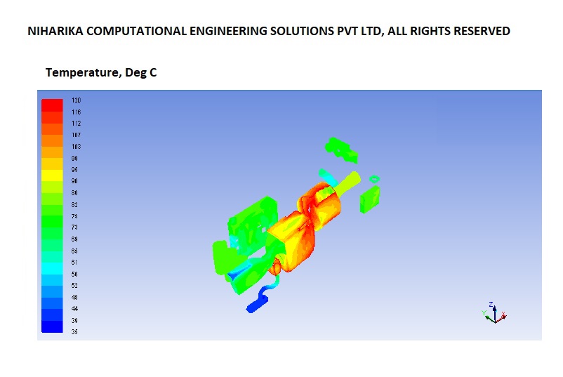
The scope of this project is to perform Computational Fluid Dynamics (CFD) analysis of the Wind Turbine Generator (WTG) unit for Siemens Gamesa Renewable Energy at the complete assembly level to evaluate the airflow distribution and thermal performance of the system and estimate the temperatures of all major subsystems. The analysis covers two configurations: (1) the existing configuration, comprising four exhaust fans installed at the top of the WTG unit and a converter refrigerant cooling fan capacity of 1.5 kW; and (2) the proposed configuration, comprising three top-mounted exhaust fans and an increased converter refrigerant cooling fan capacity of 2.6 kW. The CFD model includes all major subsystems of the WTG unit, namely the transformers, generator and slip ring system, converter panel, gearbox unit, hydraulic oil tank, and converter coolant (refrigerant) systems. The scope includes evaluating airflow patterns, temperature distribution, and the thermal behavior of these subsystems under the specified operating conditions for both configurations. A comparative assessment of the simulation results will be performed to understand the impact of the proposed cooling arrangement on subsystem temperatures and the overall thermal performance of the WTG assembly.

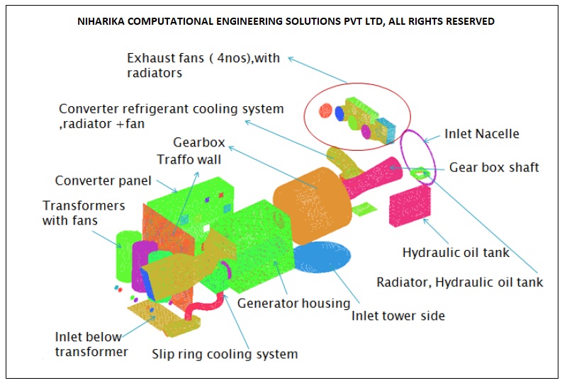
The Wind Turbine Generator (WTG) unit comprises three transformers, a generator with a slip ring system, a converter panel, a gearbox unit, a hydraulic oil tank, and a converter coolant (refrigerant) system. These subsystems generate heat during operation and are equipped with dedicated fan-based cooling systems to facilitate heat dissipation and maintain acceptable operating temperatures. The overall ventilation of the WTG unit is maintained by exhaust fans installed at the top of the assembly. These fans create a suction effect, drawing ambient air through the inlet ducts and ventilation openings. The incoming air flows through the enclosure, promoting convective heat transfer from the heat-generating components before being discharged through the exhaust outlets. The CFD model incorporates all major subsystems, inlet and exhaust openings, and associated cooling fans to capture the interaction between the main ventilation system and individual subsystem cooling arrangements. The analysis evaluates the airflow distribution and temperature profiles within the WTG assembly, enabling the estimation of subsystem temperatures and identification of potential hot spots under the specified operating conditions.
The airflow within the WTG unit is modelled under steady-state conditions. The three-dimensional, viscous, incompressible Navier–Stokes equations are solved to predict the airflow distribution and associated thermal behavior within the assembly. Pressure–velocity coupling is handled using the SIMPLE (Semi-Implicit Method for Pressure-Linked Equations) algorithm. The computational domain is discretized using an unstructured mesh comprising approximately 20 million tetrahedral volume cells. Turbulence is modelled using the k-omega turbulence model, with a fine mesh near solid surfaces to capture the flow behavior in the near-wall regions. The near-wall mesh is designed to maintain the dimensionless wall distance ( y plus) within the range of 1–5. The governing equations are discretized using second-order upwind schemes to improve spatial accuracy and capture the flow and temperature gradients within the WTG unit.

In the existing configuration, the WTG unit is equipped with four exhaust fans installed at the top of the nacelle to extract hot air from the enclosure and maintain adequate ventilation. The converter coolant (refrigerant) system is provided with a cooling fan having a capacity of 1.5 kW. This configuration serves as the baseline for CFD analysis to evaluate the airflow distribution, heat dissipation, and temperature profiles of the major subsystems within the WTG unit under the specified operating conditions.
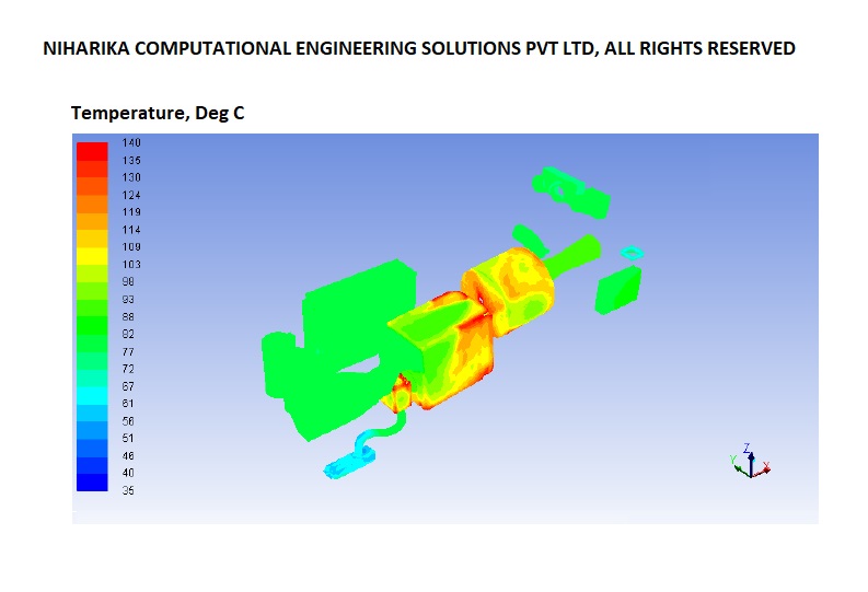
In the proposed configuration, the WTG unit is equipped with three exhaust fans installed at the top of the nacelle to extract hot air from the enclosure. The converter coolant (refrigerant) cooling fan capacity is increased from 1.5 kW to 2.6 kW to enhance the cooling performance of the converter system. This configuration is analyzed using CFD to evaluate the airflow distribution, heat dissipation, and temperature profiles of the major subsystems, and to assess the impact of the modified exhaust ventilation arrangement and increased cooling fan capacity on the overall thermal performance of the WTG unit.
We Got More
Go through All Our Case Studies
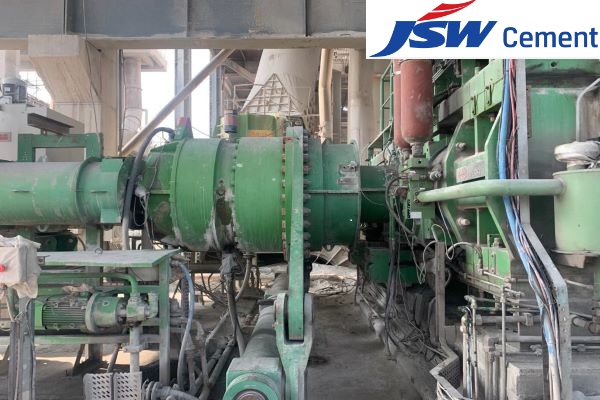
Cement grinding plant Roller shaft re-design and FEM analysis
Frequent failure of the shaft used in cement grinding units at our customers plants across India warranted an independent review of the shaft design. Niharika Computational Engineering Solutions Pvt. Ltd. (NCES) was chosen for this Independent review task using the finite element method. NCES was provided with information on the working principles of the roll press system and also information on the material used for the shaft that is in question, along with detailed drawings. To better understand the design of the shaft for various loads that it would see during normal operation, a comprehensive study was undertaken by the NCES team. This study involved using Finite Element Analysis (FEA) and performing static analysis for load distribution, modal analysis for estimating natural frequencies, rotor dynamics for checking resonance due to vibration, and dynamic analysis to estimate endurance limit under complex loading and crack initiation and propagation. NCES team has modified the shaft design and recommended a new material that addresses the frequent failure of the shaft. Read More
Structural analysis of crude oil storage tank
The scope of the work is to validate the structural design of a 32 Kilo Litre crude oil storage tank employed in the Adani Petrochemical plant. Our customer has approached us to validate the tank and cone roof design using Finite Element Analysis (FEA). We conducted FEM analysis, worked collaboratively with our customer, and enabled them to address all the minor uncertainties. In the end, we concluded that the design met all the structural requirements. Read More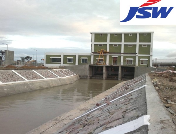
Diagnostic study to eliminate resonant vibrations in vertical Turbine Pumps at JSW-Almatti Pumping station
After the implementation of the solution engineered by the NCES team, all the pumps have been operating without any vibration issues for six months. This is similar to the condition ten years ago when Larsen and Toubro Limited handed over the pumping station to JSW Limited. Read More
CFD analysis of Multi Band Remote Radio Unit
The advent of 5G technology has brought about unprecedented advancements in wireless communications, enabling faster speeds, lower latency, and increased capacity. These advancements are associated with higher power consumption and increased heat generation in the 5G Remote Radio units.Increasing data rates and network densification require radio units to process larger volumes of data, leading to higher power consumption and heat generation. Environmental factors such as ambient temperature, humidity, and exposure to direct sunlight also impact the thermal aspects of the radio units. Read More