PROJECT DETAILS
Frequent failure of the shaft used in cement grinding units at our customers plants across India warranted an independent review of the shaft design. Niharika Computational Engineering Solutions Pvt. Ltd. (NCES) was chosen for this Independent review task using the finite element method. NCES was provided with information on the working principles of the roll press system and also information on the material used for the shaft that is in question, along with detailed drawings. To better understand the design of the shaft for various loads that it would see during normal operation, a comprehensive study was undertaken by the NCES team. This study involved using Finite Element Analysis (FEA) and performing static analysis for load distribution, modal analysis for estimating natural frequencies, rotor dynamics for checking resonance due to vibration, and dynamic analysis to estimate endurance limit under complex loading and crack initiation and propagation. NCES team has modified the shaft design and recommended a new material that addresses the frequent failure of the shaft.

FAILED SHAFTS
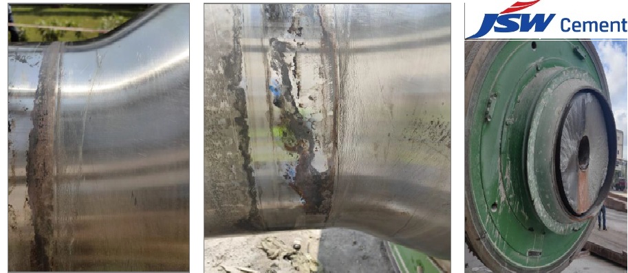
NCES was provided with information on working principles of roll press system and also information on material used for the shaft that is in question. Detailed drawings of roller shaft were provided and were used for developing finite element model. They were also provided with several images of shafts that were in different stages of failure. Some of the images were of shafts that had cracks on the surface where the failure had just begun and some were of the shafts that were completely failed and split. Figure shows sample of these images. Initial visual analysis of the images of the failed shafts indicated that the failures were all fatigue induced. To better understand the design of the shaft for various loads that it would see during normal operation, a comprehensive study was undertaken by the NCES staff. This study involved using finite element method and performing, static analysis for load distribution, modal analysis for estimating natural frequencies, rotor dynamics for checking resonance due to vibration, dynamic analysis to estimate endurance limit under complex loading and crack initiation and propagation.
FEM REPRESENTATION
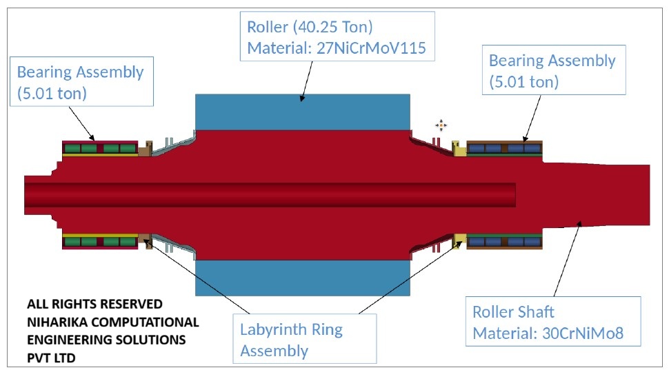
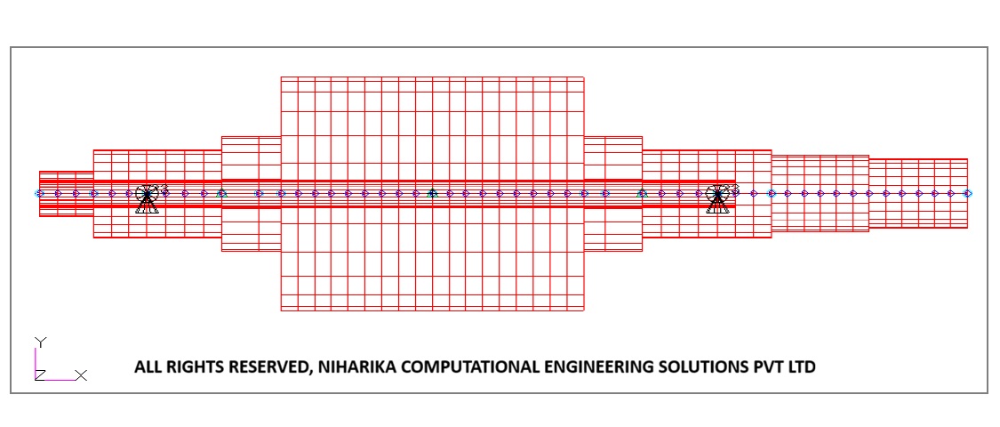
Finite element model that was developed for the above analyses in shown in this figure. Several simplifications and assumptions were made to reduce the complexities involved in developing FE model as well as to reduce computational time. Bearings were modeled as rigid surfaces and all the bolted connections were modeled as rigid constraints. Forces between shaft and bearings were modeled as friction less. Labyrinth rings were modeled with only outer surface assuming that their influence on shaft behavior is minimal.
STATIC FEA RESULTS
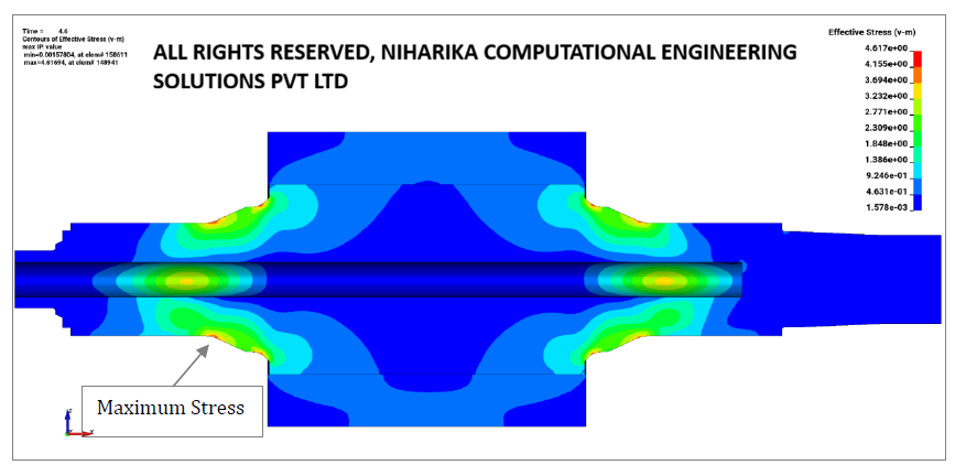
Design of any structure includes standard static analysis as the first step. To analyze the distribution of load on the structure, a steady (or static) load was applied while ignoring inertia and damping effects. While using the finite element model of the roller-shaft system as explained in previous section and applying constant gravity load, the stress distribution was calculated and is shown in the figure. It is seen that maximum stress induced in the shaft is 4.6 MPa. and at location where the diameter of the shaft starts gradually increasing from 650 mm to its maximum. Even though the induced stresses due to self-weight are very low, the stress distribution pattern shows the stress concentration point or weak section of the design.
MODAL FEA RESULTS
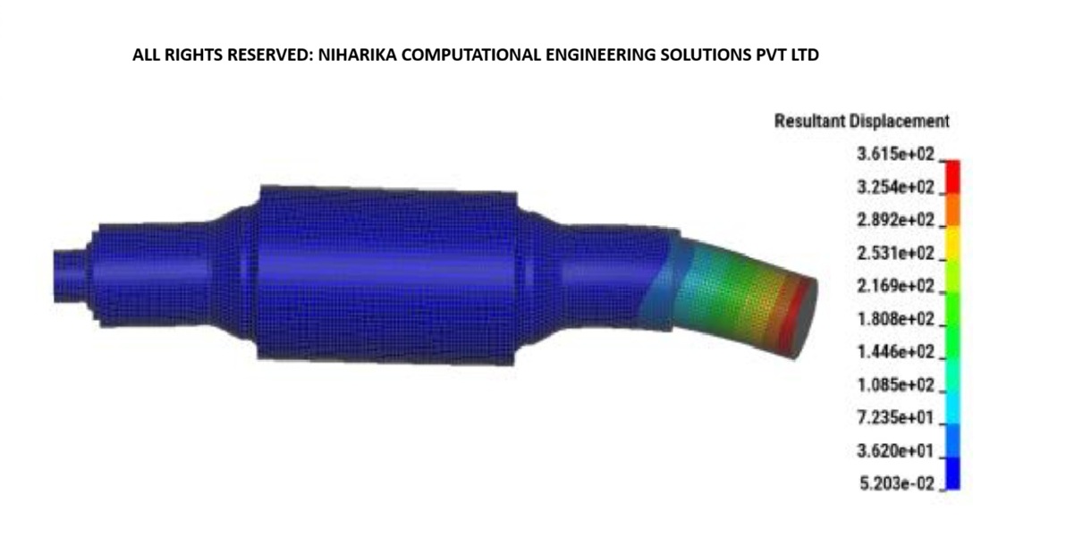
Every system can be described using stiffness matrix which gives relationship between the input (force) and the response (displacement). Depending on the mass and stiffness of the structure the system will naturally resonate at various frequencies/periods. It is important to know these frequencies of vibration so as to know that the working conditions do not excite resonance. Using the finite element model of the roller-shaft system, natural frequencies were calculated.
FEA - HYBRID LOADING CONDITION
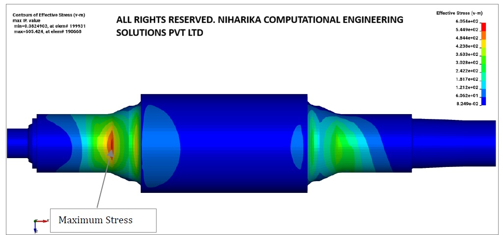
Most physical systems such as roller-shaft system in question often experience combination of different loads at the same time. In case of roller-shaft system they are, gravity load due to its own weight, torsional load applied by the dual motors and bending load due to crush-feed. In this section, induced results from these loads when applied individually as well as in combination are presented. Distribution of induced stress due to gravity load is shown previously in static analysis section. In this load case, maximum stress seen on the shaft is 4.6 MPa as shown in the figure.
ROTOR DYNAMICS FEA
A structure that has any imbalance rotated at certain frequencies can initiate resonance forces which often develop instabilities and catastrophic failure of the system. It is important to calculate these frequencies and avoid operating at those speeds to prevent failures. It can be seen that the lowest whirl frequencies are for the first four modes and are found to be 11.07 Hz. The operating speed of the roller-shaft is 15 rpm which is equivalent to 0.25 Hz. Hence the whirling of the rotor system is not expected in the operating range and will not produce oscillating forces in the rotor/support structure. The lowest critical frequency obtained by FEM is 663.5 rpm. As the operating speed of the roller-shaft, 15 rpm, is significantly lower than the lowest critical frequency there is no cause for concern of resonance.
CONCLUSIONS DRAWN FROM FEA ANALYSIS
Analyses of different loads (static and dynamic) on the system showed us the area of stress concentration. It is validated by the actual failed shafts which show similar area of crack initiation. Maximum stress developed in the shaft due to combination of different loads was about 600 MPa. This maximum stress gives 1.25 as the safety factor for the 30CrNiMo8 steel. Shaft design is slightly altered and new material is recommended based on the above described detailed FEM analysis.
We Got More
Go through All Our Case Studies

Structural analysis of crude oil storage tank
The scope of the work is to validate the structural design of a 32 Kilo Litre crude oil storage tank employed in the Adani Petrochemical plant. Our customer has approached us to validate the tank and cone roof design using Finite Element Analysis (FEA). We conducted FEM analysis, worked collaboratively with our customer, and enabled them to address all the minor uncertainties. In the end, we concluded that the design met all the structural requirements. Read More
CFD analysis of Wind turbine Generator unit
This project is executed for Siemens Gamesa Renewable Energy. The objective is to conduct CFD analysis for the Wind Turbine generator (WTG) unit at the assembly level and to estimate the temperature developed on all the subsystems We carried out CFD analysis for two configurations, a) The existing configuration consists of four exhaust fans on top of the WTG system and converter refrigerant cooling fan capacity is 1.5 KW. b) The proposed configuration with three exhaust fans at the top of the WTG system and converter refrigerant cooling fan capacity is enhanced to 2.6 KW All the major subsystems in the WTG unit, like transformers, Generator & slip ring system, converter panel, gearbox unit, hydraulic oil tank and converter coolant (refrigerant) systems are considered in the CFD analysis. Read More
Diagnostic study to eliminate resonant vibrations in vertical Turbine Pumps at JSW-Almatti Pumping station
After the implementation of the solution engineered by the NCES team, all the pumps have been operating without any vibration issues for six months. This is similar to the condition ten years ago when Larsen and Toubro Limited handed over the pumping station to JSW Limited. Read More
CFD analysis of Multi Band Remote Radio Unit
The advent of 5G technology has brought about unprecedented advancements in wireless communications, enabling faster speeds, lower latency, and increased capacity. These advancements are associated with higher power consumption and increased heat generation in the 5G Remote Radio units.Increasing data rates and network densification require radio units to process larger volumes of data, leading to higher power consumption and heat generation. Environmental factors such as ambient temperature, humidity, and exposure to direct sunlight also impact the thermal aspects of the radio units. Read More